


Technologies
Search
Thermal Management
1. Preamble
2. Typical application fields
Typical application fields for circuit boards with thermal management are LED-applications, engine control, switch-mode power supplies and semiconductor switches.
3. Influence of the PCB
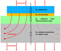
In most cases it is sufficient to take an estimation of the thermal resistor as a series connection of the partial resistors on account to the component surface area. For a more exact calculation with considering the heat spreading within the layers it is required to
use an FEM-based simulation software. In order to dissipate the heat from the inducing parts (components) out of the circuit board, the conduction (heat conduction) within the circuit board and as well the possibility of heat eduction to the environment (convection) thus need to be improved in general. That means at first a reduction of the thermal resistors within the layout and the implementation of heatsink layers for a better heat spreading and environment eduction. There are several different technological concepts for the realization of these general requirements.
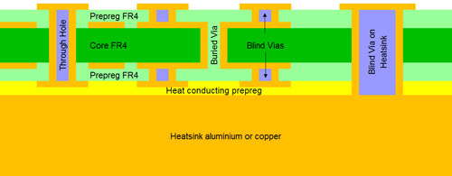
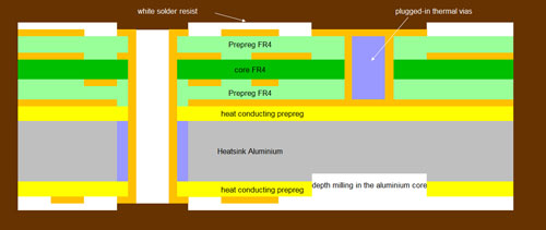
4. Thermal Vias
The biggest thermal resistor is always within the dielectric interconnection layers. The material-specific Parameter Heat Conductivity is here worse than copper by a factor of 100 (at so-called heat conducting prepregs) up to a factor of 1500 (standard FR4)! Thus, it is needed to keep those layers as small as possible and, if applicable to bypass with so-called thermal vias. This concept has well-proven especially with multi-layer switchings.
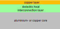
Single switchings with a low layout-complexity can often be realized with an electric layer. The thermal load of equipped components is simply led-away by a very thin and highly heat conductive dielectric fluid onto a fullsurface heatsink layer which is placed on the outside. This conventional IMS (Insulated Metal Substrate) Technology is mainly implemented in LED-applications. For this purpose, we purchase IMS-substrates in various designs (Heatsink Aluminum or copper, dielectric thicknesses, thermal conductor value of the dielectric, etc.) and finish them in our processing.
5. IMS Substrates
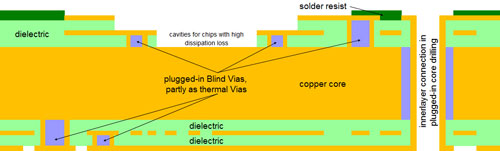
6. Possible Combination
Furthermore, there are several options for a combination, such as: e.g. multilayer switching with a metal-core, or a substrate subsequently bore from the outside, in connection with heatsink-filled vias with a random number of layers. However, the resulting disadvantage here is that in comparison to the above values the heat conductivity sinks evidently.
This results on the one hand from the combination with FR4-material (heat conductivity only approx. 0.3 W/mK) and on the other hand it is unlike harder to derive the heat from a metal-core placed inside.
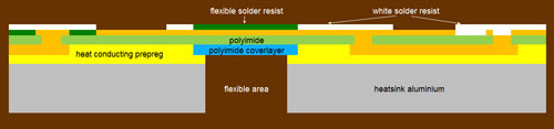
7. Special Layouts
With an increasing complexity of the switching the requirements to the technological flexibility and to the competence of the circuit board manufacturer are increasing as well. As well special layouts, such as flexible, flex-rigid or HDI/SBU-switchings are concerned more and more by the requirements regarding the thermal management. Here you demand functional and cost-optimized technological solutions. With CONTAG AG you have a perfect
partner at your side for these solutions. Our CONTAG-experts will advise and attend you throughout the process, from the construction and design phase until the prototype and series production.
8. Summary
Suitable thermal management on the printed circuit board provides the layouter with suitable solutions for the specific application. With CONTAG AG you have a perfect partner at your side. We work with you to develop technologically functional and cost-optimized solutions. We advise and accompany you from the development phase through prototype production to series production.
For further technological questions on the subject Circuit Boards please refer to our CONTAG-Team (phone +49-30- 351 788 300 or team@contag.de).
Version: B
Your personal contact
+49 30 351 788-333
team contag.de
 Technology Information "Thermal Management"